simonjackson1964
Mitglieder
-
Benutzer seit
-
Letzter Besuch
Alle erstellten Inhalte von simonjackson1964
-
 I'm so bad at doing scenery that I decided to do a layout with just scenery, to see if I could make it look good. I have to say I think it's okay as far as it goes... But then I decided to put cars on the roads. And I decided to put a timer on the junctions to make them change at "random" and direct the traffic down different roads. And I encountered two problems. 1) In order to prevent the road switching while a vehicle was on it I used the simple condition "If any vehicle is on track junction 1". Which works fine, except a semi trailer is not a vehicle, apparently. The truck was for ever loosing its trailer at the junctions. In the end I gave up and deleted the trailer. Does anyone have a way of preventing this? 2) The invisible men from Mars... Okay the spacers. They are vehicles. They are great for keeping the traffic spaced out, but they don't stay where I put them... The instructions say that the spacer should be placed between the vehicles and the clutches deactivated. But should the spacer be driving itself? Should the clutches on the actual vehicle also be deactivated? Should the vehicle be pushing the spacer? Or should the rear clutch on the vehicle be active so it pulls the spacer?
-
Ahhh. Live frog and dead frog. That sounds like a nasty thing to do to amphibians! The frog being the V where the two inner tracks meet. I'm familiar with using these in real models. Dead frog points have a plastic insulator between the rails with wires underneath to carry the current across to the switch rails. These can be switched manually because there's no electrical interference between the tracks. Live frog points have no insulation and thus have to be wired to switch electronically, with additional wiring to isolate the correct section of track.
-
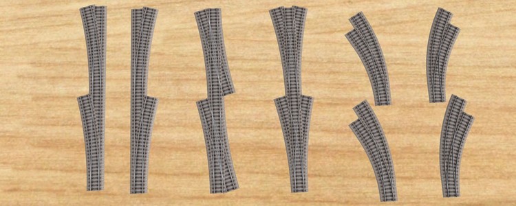
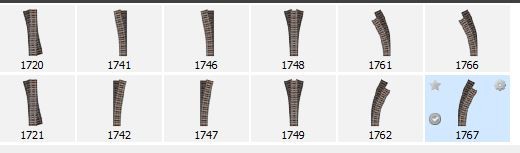
Interesting: I just tried to recreate the same effect by crossing four straight tracks at the same point. It worked - as in, I got the loco to change direction, But it was almost impossible to do by accident. I had to very deliberately set the X and Y coordinates of the track. So pretty sure it's not something that would ever be a problem. While I've got your attention though... The points (turnouts, switches) on the top are the lower number, the ones beneath are the higher number. I have so far failed to spot any difference. Is there any?
-
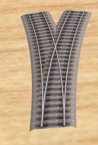
In fact it is only necessary to shorten two of the branching routes, as long as they are a matched pair. To number the points as R1 and L1 on the top track and L2 and R2 on the bottom track, (fortunately Left and Right start L & R in English and German!) if we shorten L1 and L2, and fill with a snippet of flexible track F (bending the laws of physics because with real N-gauge track that wouldn't be possible - but then with real track it wouldn't be necessary!) but leave R1 and R2 the same length, then the contacts for R1 and R2 are now joined to each other the same as for a normal cross-over. Meanwhile L1 is only connected to F and L2 is only connected to F. I've tested it and it works! L1 I reduced the "angle" to 12° then copied and pasted for L2. This method also removes the need to lengthen the straight spur on one of the tracks. Tatsächlich müssen nur zwei der Verzweigungsrouten gekürzt werden, solange es sich um ein übereinstimmendes Paar handelt. Um die Punkte als R1 und L1 auf der oberen Spur und L2 und R2 auf der unteren Spur zu nummerieren (zum Glück starten Links und Rechts L & R auf Englisch und Deutsch!), Wenn wir L1 und L2 kürzen und mit einem Ausschnitt aus flexibel füllen Spur F (Biegen der Gesetze der Physik, weil mit einer echten Spur mit N-Spur das nicht möglich wäre - aber mit einer echten Spur wäre es nicht notwendig!), aber lassen Sie R1 und R2 gleich lang, dann die Kontakte für R1 und R2 werden nun wie bei einer normalen Überkreuzung miteinander verbunden. Währenddessen ist L1 nur mit F und L2 nur mit F verbunden. Ich habe es getestet und es funktioniert! L1 Ich habe den "Winkel" auf 12 ° reduziert und dann für L2 kopiert und eingefügt. Diese Methode beseitigt auch die Notwendigkeit, den geraden Sporn auf einer der Spuren zu verlängern.
-
Ah, that explains it, thank you. And I am now going to see if I can construct what you show. By the way it is also necessary to lengthen one of the straight tracks, as you may have noticed. This is equally weird but has a logical explanation that lies somewhere in the realm of advanced geometry that I refuse to contemplate on a Sunday afternoon! Ah, das erklärt es, danke. Und ich werde jetzt sehen, ob ich konstruieren kann, was Sie zeigen. Übrigens ist es auch notwendig, eine der geraden Spuren zu verlängern, wie Sie vielleicht bemerkt haben. Dies ist ebenso seltsam, hat aber eine logische Erklärung, die irgendwo im Bereich der fortgeschrittenen Geometrie liegt, über die ich an einem Sonntagnachmittag nicht nachdenken möchte! (Translation by Google Translate)
-
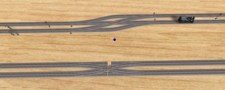
On a slightly different but related topic, perhaps either of you could solve a mystery for me? I'm trying to create what I understand is called a "Scissor" crossing. The top track formation works just fine. (The blue button just makes sure that the correct point gets changed so they all change together) But obviously, it takes more room and jinks the tracks over. The lower formation would be preferable, but it does weird things... (The gaps in the straight routes are deliberate, because I wanted to be sure the angled routes were connecting properly.) I'm using Arnold Spur N for no other reason that it's first, It looks okay and I've modelled in N since I found I could fit more into the same space as HO. So I have no idea why or what causes it, but drive a train from bottom right, it should go to top left, but instead it does a fancy (and physically impossible) pirouette and goes to top right. Drive a train from top left, it goes to bottom right. But oddly, so do trains fro the other two directions. Top Right pirouettes and goes bottom right, bottom left does a delicate swerve to go bottom right. Any ideas? Oh and I do recommend trying it out, because watching a BR 01-118 and tender pirouette like that is really entertaining! Edit to add - It does it on other track makes too. Tried it on Atlas O, and it's the same.
-
That's fine. I was wondering. I'm getting to grips with the track editor, slowly.
-
Another question, on a related subject: the Gleissperre mit Boden-Formsignal, track closure with ground shape signal. I can see how it works and why it would be used, but is this something that would only be found on a siding, or would the Gleissperre on its own be used, possibly linked to a main signal, on say, a branch line joining or crossing a main line? Or even on a main line to prevent a train leaving a station - Possibly on a slope? Next question (possibly @Henry) Your document contains this paragraph: Wer möchte, kann durch Einbau einer zusätzlichen virtuellen Sperrweiche (rot) versuchen, den Zug entgleisen zu lassen. Das markierte Gleis hat die Eigenschaft unsichtbar aus dem Archiv. If you want, you can try to derail the train by installing an additional virtual blocking switch (red). The marked track has the property invisible from the archive. I've been unable to find such an item. The locomotive runs straight through the track closure, and will only stop at the trailing point if points are locked for it... Or (obviously) if an event is set to stop any vehicle at closure.
-
SHIFT!!!!!!!! Thanks! That's what I'd forgotten!
-
Hi, it's that English guy who asks a lot of questions again... So, didn't there used to be a way to create a mountain by dragging a point up? Can't seem to find how to do that on V5...
-
Thanks guys, that's really helpful. (Does mean I'm going t have to re-do the signalling on all the layouts I've created so far though!) *eyeroll* Although as none of them have been (or likely will be) uploaded, I suppose it doesn't matter, as long as what I've got stops the trains hitting each other... Next project will have proper signalling. I hope... My biggest problem now is the damn scenery. I can never get it to look as good as everyone else does... *grumble*
-
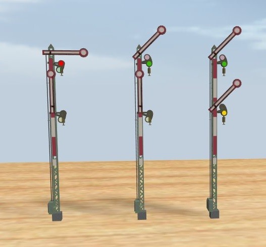
Hmm... So. basically the semaphore and orange disk are one in front of the other (with enough room for the disc to rotate). I actually found that in your original response just now. Apologies for nor reading it properly! So... The signal on the left means "Stop" (HP0). The signal in the middle means "Proceed" (HP1). The signal on the right means "Slow Speed" (HP2) (According to Google Translate). What I'm trying to understand here is when would the signal HP2 be used? You said something about on a tight curve, but if there is a tight curve surely there would be a speed limit on the track anyway? Or the signal wouldn't be capable of displaying HP1, (As per Form Signal 3). Hmm.... So I think I might have had an answer to my original question, all the way back there, but without realising it... If the point is set straight then the signal shows HP1. But if the point is set curved then it shows HP2? Presumably if the point is a Y, then again the signal doesn't show HP1? ...Moving on... I read an interesting article about the light signals. So two reds obviously means "Stop" (HP0). One green means proceed (HP1). Green and yellow (HP2) I now have to assume means proceed slowly, because there's a junction ahead.The single red with the two angled white lights (SH1) means Stop, unless you're shunting. Basically the equivalent of having a ground signal alongside (or on the post with) the main signal. But the thing that surprised me is that last one, ZS1 - that apparently means "Hey, I'm not working properly, but you can go anyway!"

-
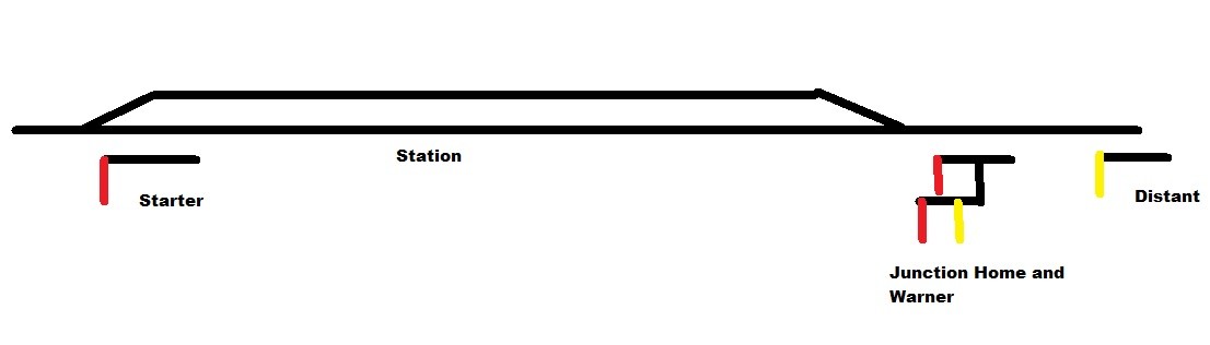
I didn't ask the question very well... The Home signal in British practice is the signal at the exit to a block. Often at the entrance to a station. As soon as the last car in a train has passed this signal the block is "Clear" and another train may enter from a permitted direction. The Starter signal is the one at the entrance to the block, often but not always at the exit of a station. As soon as the first vehicle passes the signal, the line is "blocked". and may not be entered by any other train. The distant signal is the yellow one with the notched end, and serves the same purpose as the orange disc. However as you might notice if you look ap pictures of British signals, you will often see a "main" signal - usually a home, but can also be a starter, on the same pole as a distant signal. The idea is that the main signal controls train movement at that point and the distant indicates what the next signal is. Basically this mirrors the use of coloured lights, with red indicating stop, yellow indicating proceed but be prepared to stop at the next light (two yellows can indicate stop at the next light but one) and green indicates proceed. What I'm wondering is, would the German signal with two arms extended be the equivalent of the Home being Proceed, but the advance (or Warner) being "prepare to stop". So, if the home signal is at Stop, the distant will be prepare to stop Similarly if the starter is at stop, the warner will be at prepare to stop,So the condition where a train can enter the station, but cannot leave would be signalled on the home gantry by the home signal being "proceed" and the Warner being "Prepare to stop". That's what I'm trying to get across...

-
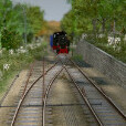
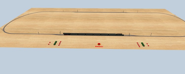
Slam the brakes on? Ha ha! It is worth noting that 90% of all train crashes ever were due to signalling errors or failures! Yes, I'm aware of signal interlocking (I did a brief stint as a trainee signalman on the Kent & East Sussex Light Railway, before a hernia put paid to that ambition!) - In fact I took my little "sample" I made for the picture above and took it the next step... Not too happy with the point controls, I'll see if I can find something better, but the red/green lights act as buttons to control the home and starter signals. The "Panic Button" just sets both trains current speed to zero. Interlocking the points and signals is my next task. Because the signalling is manual, but the trains are event driven. So, what would be shown on a Home signal to indicate that the next (starter) signal is at "Halt"?
-
Hi Goetz Thanks, that does make things clearer. I suppose the British practice of telling the driver where he's going is unnecessary, after all, it's not like he has a choice! The only time it might be important is at a large terminus like Waterloo, where the driver might need to know which platform he's being directed to, but even then it would only be so he could pass information to the passengers. If the platform is too short for the train, that's the signalman's fault and there's not a lot the driver can do about it! That said.... In the situation above it might be nice for the driver to have some advanced warning that he's going straight and not going head to head with the train coming the other way...! Driving trains is all about trust!
-
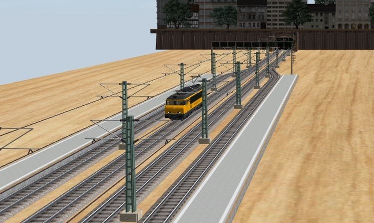
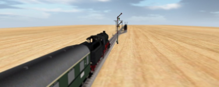
Hi. So, I know this is a largely German product, and I have no problem with that. But I'm kind-of unfamiliar with German signalling practices. So I did a bit of research and found some decent articles on the various signals in use in Germany and what they all mean. But it seems there'd something missing. In the UK, junction tracks are signalled separately. The semaphore signals above show off for the straight track with the distant signal on, and on for the junction to the right. The signal to the left is higher indicating that it is the main line. (Note the point is set to go straight...) With coloured light signals, multiple routes can be signalled more simply: A single amber light meaning proceed but expect to stop at the next light, and "take the third left", Fortunately everything there is set on, and with no view of the track, I'm not even going to attempt to decipher what each one means. But the best that I see on the online catalogue are ground signals that indicate the setting of the individual points, which would usually be used for shunting rather than main-line signalling. Please can someone point me in the right direction here? (pun intended)
-
Reminds me of when I was 8 years old and got my first train set!
-
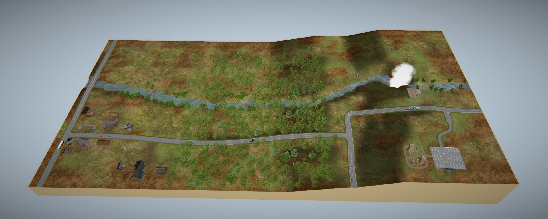
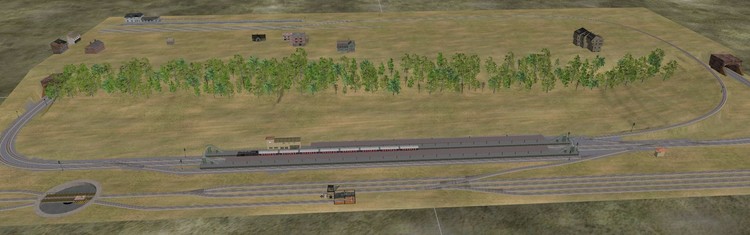
As a matter of interest... This is a work in progress, but the wooded slope was done using this plug-in - after I figured out what the translation by Google meant in the real world!
-
NOTE: Translation from German to English done using Google Translate. Any inaccuracies or badly translated idioms, please blame Monty Python’s Flying Circus. (Ich möchte, dass du meine Brustwarzen streichelst) Seriously though… Where it’s obvious what the label on the interface means (Ellipse in English is Ellipse in German, for example) I have left just the English word in the text. Where it’s less obvious to a non-German speaker, (Circle in English is Kreis in German) I have put the German word back in to make it more obvious. The origin of this plugin is here ... "Landscape design" plugin by EASY 04.2016 The plugin can be found in the catalog under the menu item "Plugins" -> "Planning". With this plugin, a number of objects can be randomly distributed over a defined area. Warning! It is relatively easy to create many objects with this program ... use it "anyway" with care! Interface: Arrange (in mm). There are three basic geometric shapes (circle (Kreis), ellipse and rectangle (Rechteck)) available, whereby the ellipse and the rectangle can be rotated around their center. The objects are placed (based on their zero point) on the profile of the baseboard(s) (-> height in the Z direction). It can be placed (horizontally) over several baseboards. In the vertical, the profile of the top board is taken as a reference. (-> hide baseboards if necessary). Example profile: Setting the objects on the height profile of the baseboard(s) Comment: For better illustration, geometrically simple objects have been used for the following pictures ... Note: If there is another object in the area to be placed, the stand area of the object is left out. Cut out areas: Circle with left out areas 1) The baseboards are provided with an index (regardless of double names) (#xxxx where xxxx is a consecutive number) 2) The size of the surfaces can be adjusted (max. 2500 mm) 3) "[in degrees] (-> rotate ellipse, rectangle in the center)" ([ in Grad] ( -> Ellipse, Rechteck im Mittelpunkt drehen)) (max. + - 90 °) -> The ellipse and the rectangle can be rotated around their center 3a) The "leading object" forms the center of the surface or the rotation Rotate surfaces: (I think the picture below is clear enough – a rectangle rotated +45° and -45°) 4) "Minimum distances" (Mindestabstände) -> A minimum distance between the objects in the X or Y direction can be specified 5) "[in%] minimum distance variation " -> Enter the spread of the minimum distance: 0 = no scatter ... 100% = scatter by minimum distance / 2 (The spread specified is the maximum value, which is multiplied by random numbers from 0 to 1) Minimum distance variation: A rectangle with zero variation gives a grid. 60% variation gives a grid but with scatter. 6) "Anzahl" "Number" -> number of objects to be set (max. 250) Note: If the selected number is greater than the number of possible points, the number is adjusted; The setting of "Number of scaling" is adjusted proportionally. 7) "Anzahl Skalieren" "Number of scaling" -> Number of objects to be scaled 7a) The scaling takes place (randomly) within the limits of "scaling factor% (min)" and "scaling factor% (max)" (Skalierungsfaktor) Note: A scaling of the object made in the “MBS” is also taken into account. (Assuming this means in the main layout settings?) Scaling (random): 50 out of 100 objects scaled from 50% to 150% One shown original size. 8) "Drehen (+ -) 0 ... xxx Grad" "Rotate (+ -) 0 ... xxx degrees" -> Rotate the objects around the Z axes (max. 90 degrees) (The rotation specified is the maximum value, which is multiplied by random numbers from 0 to 1) Rotation (random): 9) "Start" -> starts swtting the objecys. 10) "Neu verteilen" Redistribute the objects last set to possible points within the area (regardless of the position of the "lead object") Redistribute (schematic representation): 11) "Löschen" "Delete" -> Deletes the last set objects. Objektliste = Object List (fairly obvious, but…) 12) "Leitobjekt markieren "Mark leading object" -> Marks the leading object (the position of this object forms the center of the area). 13) "Objekt(e) markieren" "Mark object (s)" -> All objects from the object list are marked. 14) "Objekt(e) einlesen" "Read object (s)" -> All objects marked in the MBS (max. 5) are read. These objects are spread over the area. Notes: The "master object" is the first object in the object list. Note: By clicking on a name in the object list, the corresponding object is marked in the MBS. Important! Only the "leading object" is decisive for the position of the surface and the distribution of the objects. The positions or the distribution of the other objects is not taken into account! 15) "Gewichtung" -> "Weighting" -> e.g. 3 objects were selected "O1", "O2" and "O3" ... if e.g. the weighting 3, 1, 5 is selected, 3 times "O1", 1 time "O2" and 5 times "O3" are set ... this is repeated until the "number" is reached ... Note: The repeated weightings of all objects do not have to equal the total objects to be placed Note: If the weighting of an object is set to 0, this object is ignored. Weighting: 16) Menu item "Parameters" - "Save" - "Open" -> The settings can be saved and called up again. The file name and storage location can be freely selected. 16a) Menu item "Parameters" - "Auto Save / Open" -> The settings are automatically saved when the program is closed and loaded when the program is opened. Note: The file name is "AutoLastSettings.xml" and is stored in the same directory as the program. Annotation: Annotation: If the menu item "Auto Save / Open" is clicked (select / deselect) it is switched, but the menu item then closes immediately ... ... The checkmark showing whether it is set or not set is only visible the next time the menu item is opened. Menu item "Parameters": Note: The name, the name and the ID of the MBS project are entered as comments in the .xml file for saving the parameters. Parameter file (.xml file): Finally, a sample image of Roter Brummer ... it was his plugin wish ... Cheers EASY
-
Hi Easy. Is there an English language version of this? Gibt es eine englische Version davon? (Bitte entschuldigen Sie mein Deutsch. Ich verwende Google Translate.) [edit] Okay so I have translated it as best I can using Google Translate and common sense. See below. Any mistranslations are the responsibility of Google!
-
Answered my own question... Exporting the events to a .html file and opening that in the browser. Then <CTRL> + F to search for the string I need to find. I found where a point was being changed that was causing derailments!
-
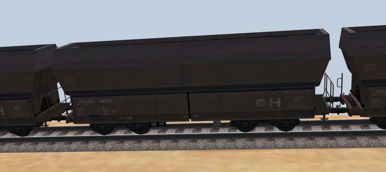
And the joke is on me... I switched to using the Falns 81 80 D DB hopper wagon It's a great rendering of it, by the way! I have a train of 18 of these guys that gets hauled from a coal mind to a power station and back. So, filling at the power station, all working. I made a little rectangle of ... Well, if I was doing this for real, I would have used plasticard, so whatever the virtual equivalent of that is - painted it with coal paint (Hey, get me a can of tartan paint? No problem! Computers are the solution to old jokes!) Popped it in the wagon at the top, linked them, and then copied the wagon 17 times. The load sequence works perfectly, dropping coal into the wagon, the when that stops the coal "card" becomes visible and hey presto! The only thing was, that, as I was watching from very close to as the wagons passed beneath the camera, I spotted a dark shadow in each one. Oops, they are already loaded. Oh well, too late now. Besides, I had to look really close to realise it. And then I took the train down to the power station to unload it... So, I knew one of those two animations opened the doors at the bottom, but not speaking (or reading) German, I had no idea what the other one did.. Until I tried it. Well look at that! It empties the wagon. I still think my coal layer is more realistic, but if only I had realised this at the start I could have saved myself the trouble! Moral of the story: Always check wa=hat all the animations do before you start!
-
I apologise if this has already been suggested - I'm quite new here. Something that I think would be really useful would be a feature where I could search for all references to any object across all the events. It would make it much easier to track errors in event coding - for example when copying an event group multiple times, it's easy to forget to change a reference. Hunting through every event in every group can be somewhat tedious. Another feature that would be really handy for testing and debugging events would be a real-time display of variable values. If this exists, I haven't yet found it. The only way to check the values of variables is to open the event wizard, and go to the "Active Variables and Timers" tab, but doing so automatically pauses the simulation. It would be handy to be able to monitor maybe a specific variable or two, to see whether they get changed when they should.
-
I keep adding little tweaks to the layout... Like I just put black smoke rising from the power station's chimney, and white steam from the cooling towers! Does anyone else find that building the layout and getting it all working the way you want is actually more fun that operating it? I find the frustration to be exhilarating, and then the joy of figuring out the solution and getting it working. Like, when I first started, I had a real problem with railcars. The train has two locomotives, one front and one back. And I found that whenever the rear loco hit a slow section of track, it would take off in the opposite direction... Of course I worked out why fairly quickly. It's going backwards. Give it a speed of +20 and it will start going forwards! I couldn't figure out a solution and couldn't understand why there are no "dummy" locos, like there are in "real" models. But, my solution to the problem of having a single loco on this layout that doesn't go around the loops but shuttles back and forth between the coal mine and the power station provided the answer. Because this loco needs to go backwards, but needs to be controlled by the same block signalling as all the others, the obvious solution was a couple of local variables giving it's main speed and slow speed, and then two more pairs, for positive and negative values that get set to the "master" pair just before it joins the main line. (Until that point, it will be under user control!) But of course it was obvious that I needed to have the same two variables on all the locos so that they were all controlled the same way... And of course, my trailing locos do NOT have them so no matter how many events they trigger they don't have a value to be set into the block speed variable. Speed remains at zero and the driving loco just drags them along! I was really pleased when I figured that out...!
-
That looks better than I came up with.... I was trying to use those before, they're the animated length ones which is really weird! But I hadn't spotted the "connect" feature. I'll give it a go. Ah, but they don't have the "Connect" feature... What I came up with may not be elegant, but it works!